


Hotline
400 666 9939
ASHRAE 110-2016 vs. EN 14175-3
Date: 2022-01-18 Source: RUANQI Classification: Resources
[editor's note: This article is translated and collated by ICT2 Jiang cuifen. Original author: Dr. Robert K. Haugen; original source: https://www.flowsciences.com/two-well-known-fume-hood-containment-tests-ashrae-110-en14175-a-comparison/. Sharing this article mainly discusses the feasibility of two test methods academically. This article only represents the author's point of view, not the company's point of view.]
Comparison of two well-known fume hood pollutant tests: ASHRAE 110 and en 14175
Dr. Robert K. Haugen
Director of Product andTechnology Development
Flow Sciences, Inc. www.flowsciences. com
2025 Mercantile Drive
Leland, North Carolina 28451
4/20/2018
1 Overview
The demand for efficient pollutant control equipment is truly international. Many manufacturers of such equipment have a global customer base. These manufacturers must demonstrate the effectiveness of their products through successful pollutant control tests.
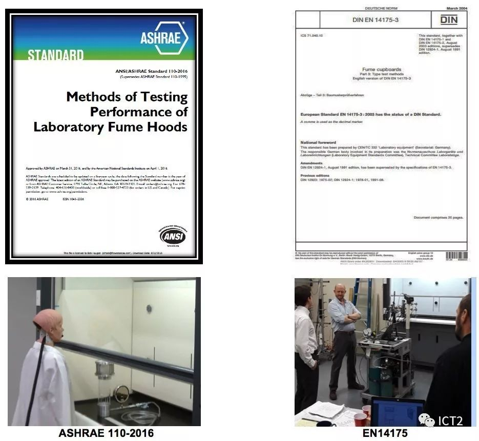
However, there are two widely used and completely different fume hood pollutant control tests. These two tests are ASHRAE 110-2016 and en 17145 - Part 3. The former was developed in the United States and the latter was Pan European.
This fact often confuses the international comparison of the two products, and their effectiveness is evaluated by different test methods. This situation will be more serious if these products participate in the same bid evaluation process.
The world map shown in the following figure describes the distribution of pollutant control test methods. Countries that use these two standards (orange stars) pose unique problems for fume hood manufacturers.
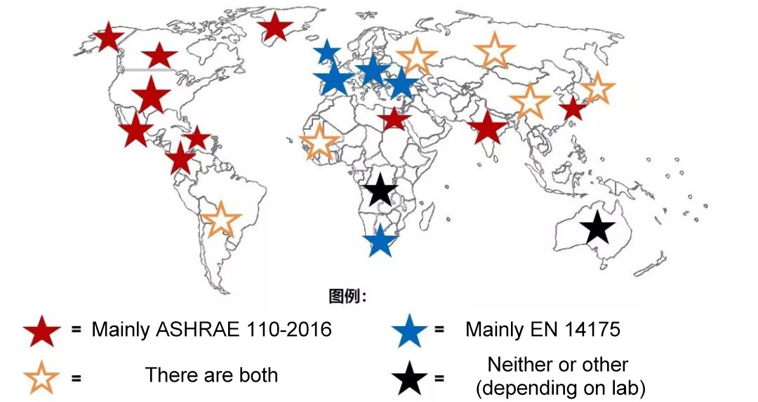
The above map clearly indicates the test standards widely used in each area. The wider area (orange stars) uses both standards. When two pollutant test standards conflict in these areas, comparing the pollutant control results of two different test products will cause serious commercial and competitive problems. Since both tests are so different, we should try to reach a consensus on how to choose products evaluated using these different criteria. Let's take a closer look at these standards first.
2 Two pollutant control test methods:
A. ASHRAE 110-2016
Ashrae110-2016 test can be traced back to the research report issued by the American Industrial Hygiene Association (Knudson and Caplan) in 1982. [1]
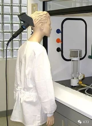
The surface wind speed of the fume hood is measured by the hot air velocimeter and the plane wind speed grid specified in Section 6.2 of the standard. SF6 is released in the fume hood, and the amount entering the breathing area of the dummy is measured by infrared spectrophotometer or ionization technology. The basic setting is shown in the following figure: [2]
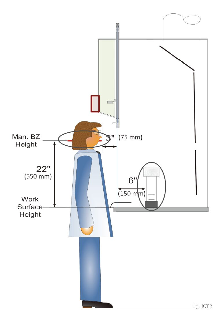
Dummy and release locations
Ashrae110-2016 test method uses 100% sulfur hexafluoride as tracer gas. The supply pressure of the gas releaser (high circle) is 30 psi and the diffusion rate is 4 LPM. The test was carried out with the manikin for 5 minutes, and the SF6 concentration in the breathing area (wide circle) of the manikin was recorded. The SME (sliding door movement effect) test is conducted for a total of two minutes, including opening and closing the vertical sliding door twice within a 30 second interval within two minutes. Test and record the concentration of SF6 in the respiratory area of the manikin.
ASHRAE 110 fume hood test, picture from chipalbright
Although ashrae110 does not define a pass fail level for testing, AIHA Z9 5 specify a pass / fail level of tracer gas in the average breathing area of 0.05 ppm. 3
B. EN 14175; Part III 3
EN 14175part3 and ashare 110 are both methods for measuring fume hood pollutant control, but they are very different in equipment and calculation.
EN 14175 has six parts:
*Terminology of hoods
*Hood safety requirements
*Hood containment testing
*Testing on site methods
*Installation & maintenance
*VAV performance testing
We will only focus on Section 3, which defines the evaluation of fume hood pollutant control and performance characteristics.
The test method of EN 14175, Part 3, evaluates and reports the leakage level of tracer gas. It also produces a series of unitless numbers called pollutant control factors, which represent the product of the tracer gas flow in the fume hood divided by the exhaust rate multiplied by the concentration of leakage tracer gas. In most written reports today, leakage tracer gas concentrations and / or pollutant control factors are used to quantify pollutant control performance.
EN14175; Part 3 test uses a 10% sulfur hexafluoride nitrogen mixture with a total release rate of 2 LPM for internal plane test (using a 9-point diffuser sampling array); The rate of external plane and robustness test is 4.5 LPM, and the fume hood exhaust rate flow for ventilation efficiency test is [(5 - 8) / 1000000].
These release rates of en are much lower than the 100% sf6,4 LPM release rate used for ashaer 110 test; As shown in the following table:
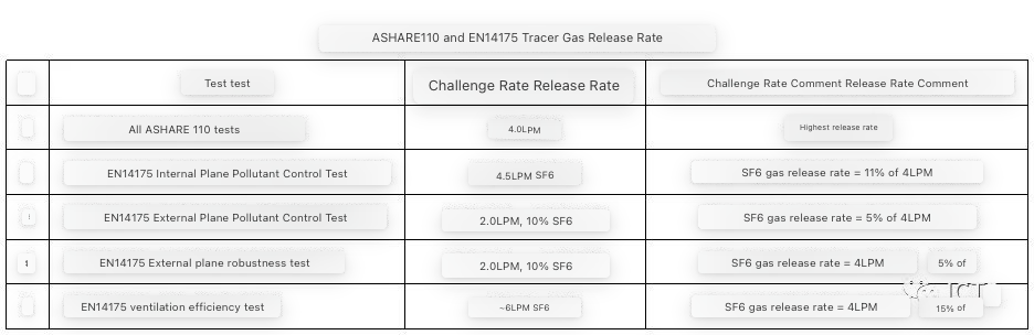
The release rate of 10% concentration of SF6, 2-6 LPM is only 5% - 15% of that of ashare110 100% SF6, 4 LPM.
3、 EN 14175 test details:
1) Gas diffuser array for external pollutant control, robustness and air exchange efficiency testing.
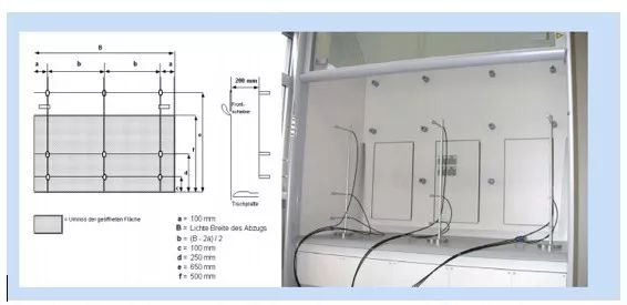
Diffuser for external pollutant control, robustness and air exchange efficiency test
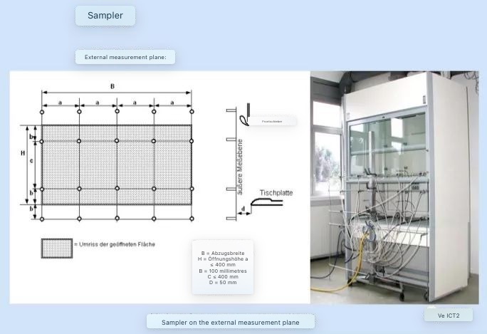
2) External sampling array and Sampler:
"External plane" is defined as the outermost part of the fume hood frame, which supports the sliding door and consists of various sampling points according to the size of the sliding door opening.
3) Inner plane sampling array and inner plane containment Diffuser:
9 internal sampling points and 1 releaser are placed on a device, which is placed at several positions on the plane of the window frame of the fume hood. The releaser (circled) for this test is located in front of the sampling grid on the same component. The sampling port is on the plane of the window frame.
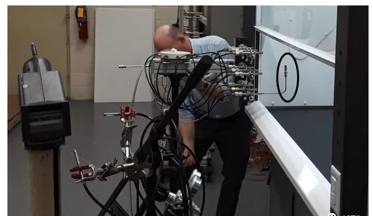
The sampling array / diffuser is aligned with the SAF t flow fume hood face
4) Sensor
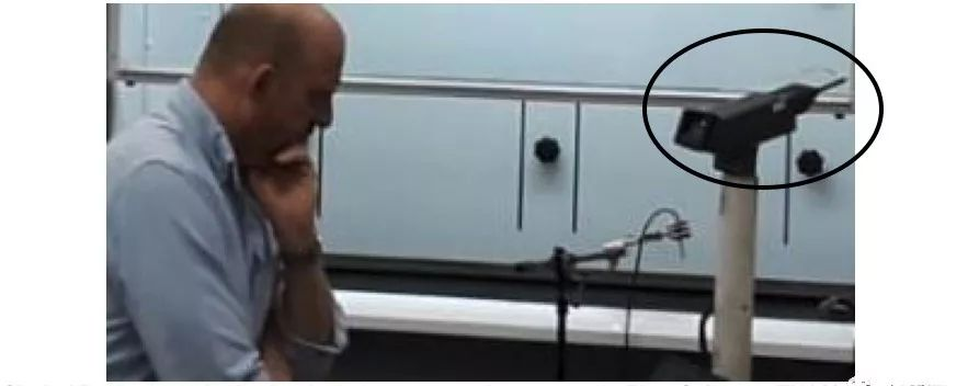
The circle part is an ionization leak detector used as a sensor in the flow Sciences en 14175 test. During the test, the tip tube of the diffuser is connected to the sampling device.
The gas analyzer used in en 14175 is roughly described in section 5.3, and the requirements are as follows:
a) Detection level of 10-8 volume ratio or less (10 ppb by volume, or 0.01ppm);
b) Time constant less than 15 seconds;
c) Data recording capability to read every two seconds or less;
d) For the test of flow Sciences, an ionization leakage detector conforming to the provisions of point a-c (as shown above) is used.
5) Robustness test
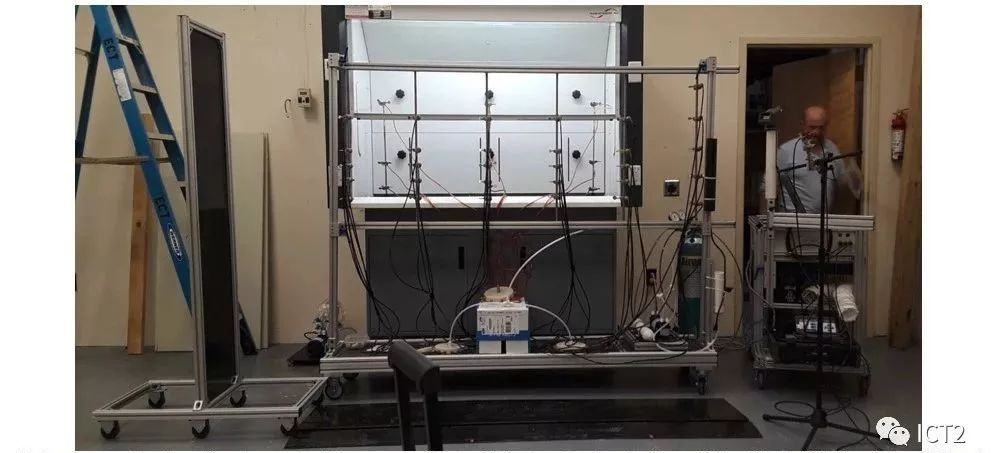
Robustness test equipment using exposure control technology of SAF t flow fume hood, CA, NC
For this test, the sliding door shall be set to the specified opening position. After 60 seconds of tracer gas release, the black rectangular wheeled trolley (see the left figure above) moves back and forth in front of the fume hood for 6 times, and the moving path should start and end at 600mm on both sides of the fume hood. The time between each intersection should be 30 seconds. Measure and record the test gas concentration. When the rectangular movement stops, record the measurement signal of the gas analyzer for 30 seconds.
6) Ventilation efficiency test
The ventilation efficiency test is measured by flow rate. The gas concentration in the fume hood is 5 ~ 8 ppm, which is measured at the equipment airway collar. When the steady-state concentration is reached, turn off the gas. The concentration / time data are recorded until the SF6 concentration in the indoor fume hood reaches 20% ~ (1 - 2ppm) of the steady-state value.
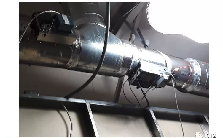
SF6 concentration test at the exhaust port near the airway collar
Next, the actual pollutant change rate is solved, λ, use this equation: [In Ci(t=ti)-In Cf(t-tf)]/△T = λ
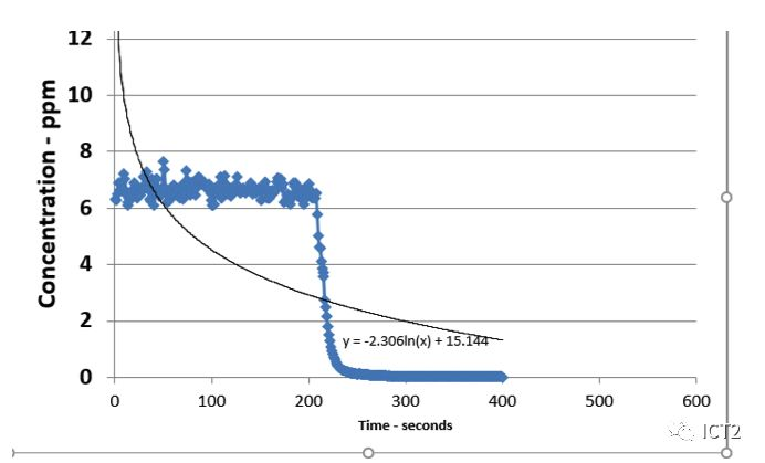
Concentration versus time for 6-foot saf t flow fume hood during ventilation efficiency test
Then, the efficiency number is calculated as the ratio of the observed air change rate of the equipment to the ideal air change rate. Since this figure does not assess pollutant control and the relationship with fume hood efficiency is unclear, it will not be discussed further in this white paper.
7) Summary
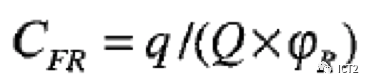
Record the average readings of all pollutant control test techniques mentioned above and apply them to the following pollutant control coefficient formula:
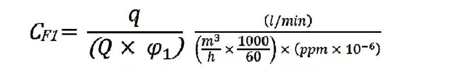
q... tracer gas release rate (SF6 - note that the tracer gas release rate is only 10% of the test gas release rate, because the mixed gas is composed of 90% N2 and 10% SF6)
Q... fume hood extraction rate
Φ 1... Average tracer gas volume fraction, rounded to two decimal places
Pollutant control factors are dimensionless; As long as all involved variables and consistent units are used, as shown in the figure, the units under this provision will be offset.
8) Pass - fail en 14175 data level
The en standard states that there are no limits. German chemical industry professional association, technical committee chemistry, July 29, 2003, inspected and evaluated the safety requirements of fume hoods for testing volume flow to determine whether they meet the effective limits.
BG Chemie, technical committee chemistry, 29 March 2003, limits for fume hood testing according to en 14175-3:2004.
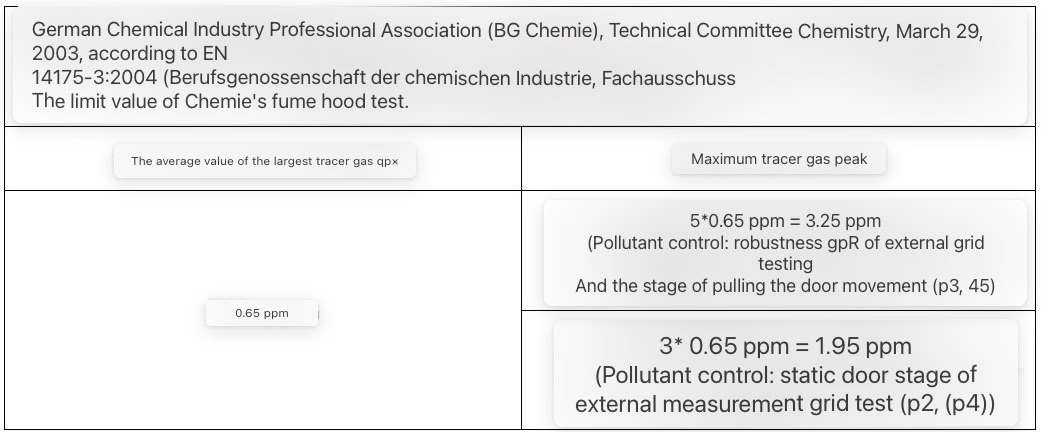
Note that it is customary in many European countries to use commas instead of decimal points for the data on the German chart. For the measured values on the internal measurement plane, the French NF xpx 15-203 gives the limit value of the average concentration value of each measurement point of 0.1 ppm.
It should be noted that most published pollutant values for commercial products are well below the limits expressed in the two sources cited above. The data published by most fume hood manufacturers did not detect any undetected tracer gas values during any test. This is also the experience of flow Sciences in this test!
9) Springer 6 expressed several problems by using the formula for calculating the pollutant control factor. Remember, the larger the CF, the better the contaminant control should be. Consider the following:
a) For most commentators, the term "pollutant control factor" means a number whose number represents the degree of control. In fact, CF combines the capacity contained with the amount of exhaust used by the system.
10) What do you actually see on site when you get the data and calculate the CF?
This is data sheet [4] using BS EN 4175 Part 3 procedures on actual fume hoods.
The exhaust rate q is in the denominator of this calculation. Therefore, the equation containing the factor gives a larger (better) number and a lower exhaust rate.
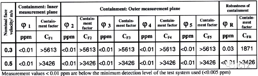
You can see that CF "magic numbers" 5613 and 3426 can be seen everywhere, because the detection of SF6 is zero, but "zero" has been replaced by the detection limit of the instrument of 0.01 ppm! Please also note that the non-standard uses ">" to distinguish the four significant figures in the pollutant control factor.
On this table, the lower surface wind speed of 0.3m/s shows a "better" pollutant control factor than 0.5m/s. This figure has been higher, and SF6 escaping due to the decrease of exhaust volume is still undetectable. This anomaly gives a misleading impression that the pollutant control characteristics are improved at lower surface wind speed.
Ali BICEN and others tried to stratify pollutant control factors into schemes as follows: [5]
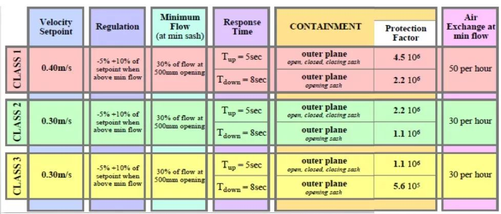

Note that the lower the trend of the external plane pollutant control factor (protection factor), the lower the surface wind speed (i.e. grade) of the fume hood. (Level 1, level 2, level 3, lowest level) this rectangular plot scheme shows that it is expected that higher surface wind speed will produce higher pollutant control factor (greater quantity), but as we can see from the example of 10 above, experiments and observations have proved that this is not usually the case!
Steffen Springer of Waldner clearly illustrates the inappropriateness of pollutant control factors using the analysis I repeat below, starting with the formula for calculating the previously defined factors: [6]
He made the following comments:
1) The structure of the equation is very simple.
2) Theoretically, the results mean that the higher the factor, the higher the pollutant control performance of the fume hood.
3) The size of the pollutant control factor depends on three values: a) Flow rate of tracer gas; b) Extract the flow rate of the fume hood; c) The average tracer gas concentration inside and outside the fume hood (the latter is the only value in this equation related to the capacity of the fume hood).
4) According to en14175, CFR shall be rounded to the nearest integer and must "if the result is limited by the detection limit of the instrument"
5) It's fun here now! For Q, the tracer gas flow rate is always constant (specified in en 14175) and the detection limit of the assumed measuring equipment is 0.01 ppm. The only remaining variable is the exhaust volume of the fume hood, because there is no detectable tracer gas escape. Is this result (CF calculated as mentioned above) suitable for objective comparison of fume hood enclosure?
Springer does not believe that the pollutant control factor is suitable as an objective indicator of the pollutant control performance of the fume hood, unless all models are tested under the same conditions, have the same extraction volume and the same test equipment. If only one of these variables is different, the accountant calculates different pollutant control factors for the same fume hood performance! Therefore, users cannot select fume hoods with good pollutant control performance according to pollutant control factors.
These problems with CF led to the use of EN 14175-3 by evaluators based on the escaping tracer gas( φ) Ppm to evaluate the fume hood, not the pollutant control factor CF! [7]
The remaining problem is that most en 14175 tests show that no tracer gas escapes under any of the above many tests. In other words, en 14175 has a large difference in the performance of fume hoods from one design to another.
Andy sinnamon responded to this view at LinkedIn. He said: "(my company) experienced this process not long ago. The lack of manikin and diluted tracer gas makes most of any fume hood design can pass." [8]
I agree that the performance conditions of the test under different wind speeds vary greatly, but I'm not sure whether the test can detect the faulty fume hood, because we may not see such a test release.
4 Summary of major issues in en 14175
1) En14175 device complexity:
The most accurate way to judge the performance of the fume hood is by evaluating "pollutant control", φ, CF is not a useful factor.
Due to the complexity of equipment, en14175-3 pollutant control test is usually performed only in the design stage (in the test laboratory). The actual construction practice has evolved into a fume hood for field commissioning through a simple "test" rather than part of EN 14175 7. [9]
The only case where the en 14175-3 test is performed on an installed fume hood is when other laboratory conditions raise doubts about the operation of the fume hood. "For example, when smoke tests indicate turbulent air flow in the fume hood (although the average surface wind speed is acceptable), and complaints about unpleasant odors emitted from the fume hood (although the surface wind speed measurement is satisfactory)." [10]
2) The meaning of pollutant control factor CF is unclear:
Fume hoods are designed to protect people from the use of hazardous substances from exhaust gases. According to the design and the amount of air extracted, any sealing device shall be able to keep the dangerous smoke inside and protect people in front of the opening of the equipment. It is said that en 14175-3 calls it "pollutant control factor" and describes how the fume hood is "effective". The fume hood can control pollutants with less air, and the greater the pollutant control performance coefficient should be.
However, undetectable escape tracer gas levels are factors that lead to uncertainty, which is not comparable to other situations using different detectors. Therefore, if detectors with different sensitivities are used, two identical fume hoods with the same amount of extracted air and the same opening in the front can have different pollutant control factors.
In the selection of smoke control devices, the safety of operators (a small amount of escaping smoke) is the most important, rather than the algebraic combination of pollutant control and exhaust volume data. In the author's opinion, the pollutant control evaluation should not use mixed values such as pollutant control factors to quantify the performance of fume hoods.
Therefore, the author believes that the focus in en14175-3 should be the escape tracer gas detected at the specified surface wind speed( φ), Not the contaminant control factor (CF).
Cambridge University pointed out that "the type test carried out according to en14175-3 obviously meets the ideal conditions. This means that even the frequent interference will not be taken into account. If any slight interference occurs, the fume hood with applicable very low surface wind speed will explode." eight
As mentioned earlier and pointed out by egbertdietrich, unless all models are tested under the same conditions, have the same extraction volume and the same detector equipment, the pollutant control factor is not suitable as an objective indication of fume hood pollutant control. Only one of these variables is different, which will lead to different pollutant control factors. In fact, the pollutant control factor cannot enable the user to select the best fume hood according to the value of CF. [11]
3) The performance of the fume hood cannot be distinguished.
Unless we can better measure the escaping tracer gas, the published data of almost all fume hoods tested with en 14175-3 will produce the same results for all escaping tracer gas tests. Fatal Frame. (i.e. 0.00 ppm)
My experience is that ashrae110-2016 usually shows measurable low tracer gas escape. The ability to generate limited readings enables developers to adjust the design to some extent and obtain data that shows improved performance. [12]
5 ASHRAE 110-2016 and en14175 Part 3 Comparison
Summary table

The authors believe that both tests can be improved. The ASHRAE 110-2016 test appears to have greater SF6 challenges, produce more distinguishable results, and is an easier test to perform in the field.
En14175-3 test measures more potential pollutant escape points. It also has standardized robustness challenges, using flying rectangles to simulate walking. The following table summarizes many of these test comparisons.
6 The influence of two standards on brand competition
Companies engaged in international business must be prepared to test the performance of fume hoods and specify any pollutant control tests as appropriate. Both pollutant control tests have their unique advantages and disadvantages.
Because tests are so different, it is foolish to convert one test data into the expected readings of other test procedures.
Comment objectivity. The large number of "ASHRAE 110" in the above figure reflects that the author mainly uses ASHRAE 110-2016 test throughout his career. It should not be regarded as "proving" that one test is superior to another.
Others should not be biased in their commercial commitment to one test or another.
Therefore, we should try to establish a single standard for the world of laboratory construction in the 21st century. No matter where the laboratory is located, such standards will help evaluate pollutant control products in a level playing field for all competitors.
7 Reference note
1. Influenceof room air supply on laboratory hoods, October 1982, Knowlton J. Caplan,Gerhard Knutson, American Industrial Hygiene Association Journal
2. ASHRAE110-2016, p. 13.
3. ANSIAIHA Z 9.5 – 2012, section 6.1.2.7, p 79
4. Typetesting of fume hood according to EN 14 175-3:2004, Institut furIndustrieaerodynamik GmbH, Certificate No. 1/FC-Z81/P3/06/13, 2013
5. Instituteof Local Exhaust Ventilation Engineers – Information Day – 17 May 2016,PowerPoint presentation, Melvyn Sargent, Lab Containment Services LTD
6. BSEN 14175-3:2003 Containment Factor deciphered, Steffen Springer, Jan. 2011,PowerPoint presentation.
7. EgbertDittrich, The sustainable Laboratory Handbook, Wiley, 2015
8. FumeHoods, Guidance for Safe Use, University of Cambridge, October2016 https://www.safety.admin.cam.ac.uk/files/hsd029c.pdf
9. Universityof Birmingham Health and Safety Department, Hazardous Substances PolicySchedule 3.8, Supplement 1, https://intranet.birmingham.ac.uk/hr/documents/public/hsu/hsupolicy/hs15/HS38LEVSupplement1.pdf
10. AirChange Measurements Using Tracer cases, Chemistry, Emission Control,Radioactive Pollution and Indoor Air Quality, 2011,David Laussmann and DieterHelm
11. https://www.linkedin.com/in/robert-haugen-22918546/detail/recent-activity/shares/
12. TheFume Hood Product Life Cycle: A Cost of Ownership Analysis Robert K. Haugen,Ph.D., Director of Product and Technology Developmen, Flow Sciences,Inc.10/31/2017