


Hotline
400 666 9939
China Machinery Industry Standard Exhaust Cabinet JB / T 6412-1999
Date: 2022-01-18 Source: RUANQI Classification: Resources
#This article is reproduced from the standard exhaust cabinet of China Machinery Industry JB / T 6412-1999, which is only for learning and exchange in relevant industries and is not used for commercial purposes. If there is infringement, please contact to delete#
Previous remarks
This standard is a revision of ZB j72 049-90 types and basic parameters of exhaust cabinets, JB / T # 5150-91 test methods of exhaust cabinets and JB / T # 6412-92 technical conditions of exhaust cabinets.
This standard replaces ZB j72 049-90, JB / T # 5150-91 and JB / T # 6412-92 from the date of implementation.
This standard is proposed by and under the jurisdiction of the national Refrigeration Equipment Standardization Technical Committee.
This standard is drafted by Tongji University and Yixing Zhanhong environmental protection equipment Co., Ltd.
Main drafters of this standard: Li Qiangmin, Cao Qiuping.
1 Scope
This standard specifies the type, basic parameters and dimensions, technical requirements, test methods, inspection rules, marking, packaging and storage of exhaust cabinets.
This standard is applicable to factory manufactured exhaust cabinets.
This standard is not applicable to local exhaust hoods in industrial ventilation systems.
2 Reference standards
The provisions contained in the following standards constitute provisions of this standard through reference in this standard. At the time of publication of this standard, the editions shown are valid. All standards will be revised. All parties using this standard should explore the possibility of using the latest versions of the following standards.
GB / T 13306-1991 label
JB / T 9065-1999 general technical conditions for packaging of cooling, heating and ventilation equipment
JB / T 7246-1994 appearance quality of cooling, heating and ventilation equipment
3 Definition
This standard adopts the following definitions.
Control concentration
Determine the discharge index of exhaust fume hood. When the exhaust cabinet operates normally, adjust the flow of the tracer gas releaser in the exhaust cabinet to 4.0 L / min, and the concentration of SF6 tracer gas measured by the breathing belt of the operator in front of the exhaust cabinet.
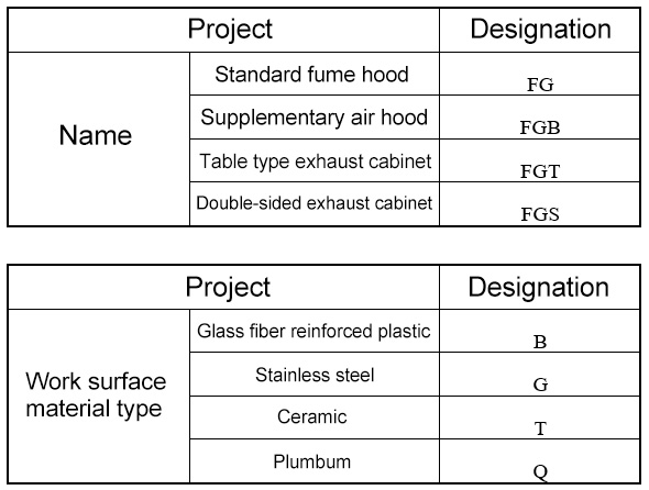
4 Type
4.1 Exhaust cabinets are divided into standard type and make-up type according to air distribution form. According to functional requirements, it is divided into desktop exhaust cabinet and double-sided exhaust cabinet. According to the material of worktable, it is divided into FRP, stainless steel, ceramic and lead.
The code of exhaust cabinet type shall comply with the provisions in Table 1.
Table 1
4.2. The model of exhaust cabinet is composed of capital Chinese pinyin and Arabic numerals. The specific expression method is as follows:

Model example:
FGB – 120B make-up air exhaust cabinet, FRP worktop, overall width 1200 mm
FG – 150G standard exhaust cabinet, stainless steel worktop, overall width 1500 mm
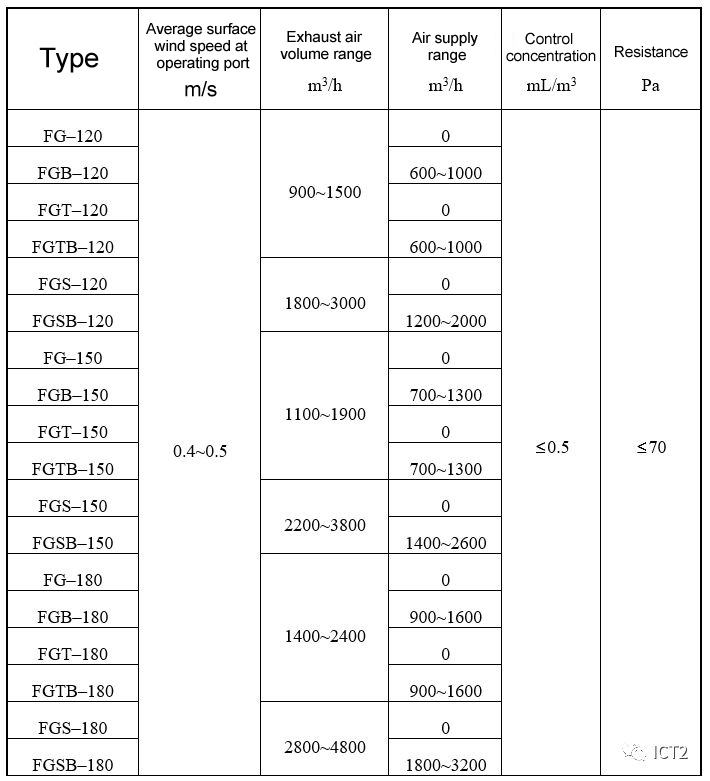
5 Basic parameters and dimensions
5.1 the performance parameters of exhaust cabinet shall comply with the provisions in Table 2.
Table 2
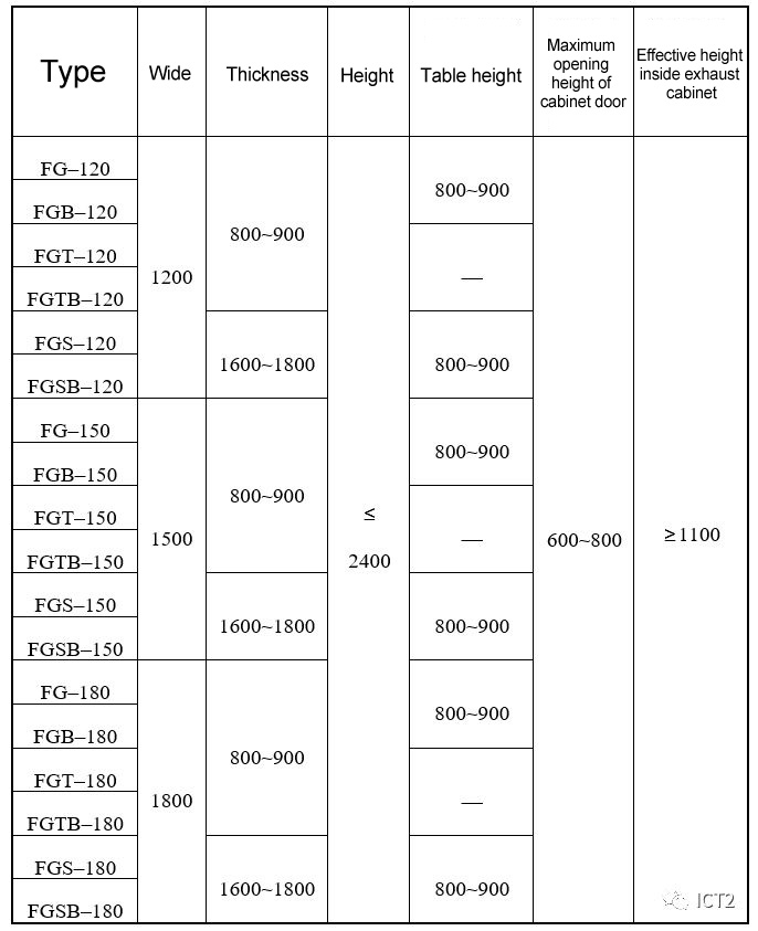
5.2 Dimensions
The dimension parameters of exhaust cabinet shall comply with the provisions in Table 3.
Table 3 unit: mm

6 Requirements
6.1 The exhaust cabinet shall meet the requirements of this standard and be manufactured according to the drawings and technical documents approved by the specified procedures.
6.2 The surface wind speed of the exhaust cabinet shall be evenly distributed, and the deviation between the maximum and minimum values and the arithmetic mean value shall be less than 15%.
6.3 The control concentration of exhaust cabinet shall be less than 0.5 ml / m3.
6.4 The resistance of exhaust cabinet shall be less than 70 PA.
6.5 The allowable deviation of the overall dimension of the exhaust cabinet is ± 3 mm.
6.6 The allowable deviation of the effective height inside the exhaust cabinet is ± 3 mm.
6.7 The flatness of the exhaust cabinet shall not be greater than that specified in Table 4 in the full length range.
Table 4 unit: mm

6.8 The paint quality of the exhaust cabinet shall be harmonious and durable in color, with strong adhesion of the paint film and firm combination. There shall be no defects such as bubbles, flow marks and crepe lines. After the test according to the method in 7.8, the number of falling off grids of the paint film shall not exceed 17%.
6.9 The operating door of the exhaust cabinet shall be easy to start without jamming, and can stay at any position within the travel range.
6.10 The working surface of the exhaust cabinet shall slope to the pool.
6.11 The exhaust cabinet shall be equipped with lighting equipment, fan switch, power socket, indicator light, water supply and drainage device, and the orifice of air supply pipeline shall be reserved.
6.12 The insulation resistance between electrified body and exposed metal is greater than 2 MW, and there is no breakdown or flashover under 1500 V test voltage for 1 min.
6.13 The exhaust cabinet is made of FRP, sheet steel or stainless steel and other corrosion-resistant composite materials.
6.14 The oxygen index of FRP members shall be greater than 27.
6.15 The surface in contact with corrosive media in the exhaust cabinet shall be made of acid, alkali and high temperature resistant materials.
6.16 The appearance quality of the exhaust cabinet shall comply with the relevant provisions of JB / T # 7246.
6.17 When the power supply voltage deviation is ± 10%, the exhaust cabinet shall be able to start normally.
6.18 The standard parts, outsourced parts and purchased parts of the exhaust cabinet shall comply with relevant regulations, and the certificate of conformity shall be attached.
6.19 Under the condition that the user complies with various provisions in the product manual, the actual service time shall not exceed 12000 h within 18 months from the date of delivery by the manufacturer. If the product is damaged or cannot work normally due to poor manufacturing quality, the manufacturer shall repair or replace it free of charge.
7 Test method
7.1 Flow display test
7.1.1. Test conditions
The test shall be conducted indoors, and there shall be no transverse airflow interference exceeding 0.1 M / s within 1.5 m from the exhaust cabinet.
7.1.2. Reagent
Titanium tetrachloride reagent.
7.1.3. Test steps
Place the exhaust cabinet door at the maximum opening, draw a straight line parallel to the cabinet door on the working table, inner wall and inner top surface of the exhaust cabinet with a cotton swab dipped in titanium tetrachloride (TiCl4), which is 150 mm away from the cabinet door. Draw a circle with a diameter of 200 mm on the back wall of the exhaust cabinet, and the center of the circle is located at the geometric center of the cabinet wall, The surfaces of all equipment in the cabinet are coated with titanium tetrachloride. When the exhaust cabinet operates normally, all white smoke shall be discharged through the exhaust outlet without overflow.
7.2 surface wind speed test
7.2.1. Test conditions
Same as 7.1.1.
7.2.2. Test instruments and materials
Hot bulb electric anemometer, record form, adhesive tape paper, thin wire and 2m steel tape.
7.2.3. Test steps
Open the regulating valve on the upper part of the exhaust cabinet, set the cabinet door at the maximum opening, start the exhaust fan and adjust the outlet valve of the exhaust fan, measure the section wind speed of the operation port with the hot bulb electric anemometer within the calibration validity period, and the average wind speed is 0.4 ~ 0.5 m / s.
The section of the operation port is divided into at least 16 rectangular survey areas according to figure 1, the area of each survey area shall be less than 0.09 m2, and the survey points shall be set at the diagonal intersection of each survey area.
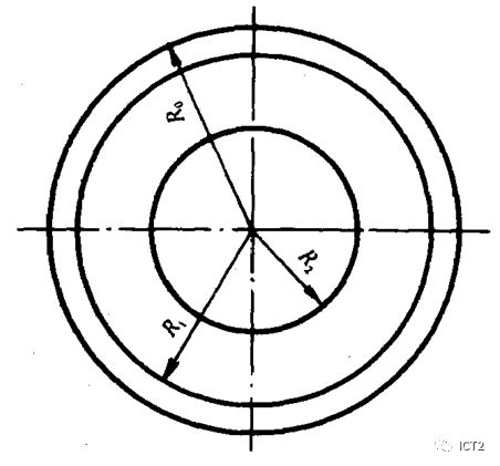
Figure 1
7.3 measurement of make-up air volume
7.3.1. Test instrument
Hot bulb anemometer.
7.3.2. Measurement method
Adjust the air supply valve and measure the make-up air volume of the make-up air exhaust cabinet with the hot bulb electric anemometer. The layout of the measuring points on the section of the air supply pipe is shown in Figure 2.
R0—Radius of supply air duct(mm); R1=0.866 R0; R2=0.5 R0
Figure 2
7.3.3. Commissioning requirements
Make up the air volume to the rated value.
7.4 Concentration test
7.4.1. Test conditions
7.4.1.1 Laboratory ventilation conditions
The air supply and exhaust of the laboratory and the exhaust of the exhaust cabinet shall be normal and meet the requirements of 7.1.1.
7.4.1.2 Conditions of exhaust cabinet
The door of the exhaust cabinet shall be fully opened. For the make-up exhaust cabinet, the make-up air system shall be in operation, and the make-up air volume shall be adjusted to the rated value.
7.4.1.3 The background concentration of tracer gas in the test room shall be controlled below 10% of the control concentration of exhaust cabinet.
7.4.2. Test instruments and materials
Anemometer: range: 0.05 ~ 10 m / s.
Release device: see Figure 3.
Detector: measuring range: 0.01 ~ 100 ml / m3, and the response time shall not exceed 10 s.
Automatic recorder: the reading accuracy is ± 0.5% of the full range.
Tracer gas: sulfur hexafluoride (SF6).
Mannequin: three dimensional dress, height 168 cm ± 6 cm, shoulder width 43 cm ± 2 cm, respiratory belt height 150 cm, shoulder height 138 cm ± 6 cm.
Accuracy requirements of detector reading:
± 25% when the concentration of tracer gas is 0.01 ~ 0.1 ml / m3; When the concentration of tracer gas is more than 0.1ml/m3, it is ± 10%.
When the concentration of tracer gas is more than 50 ml / m3 and the reading can be repeated, it is ± 1%.

1 - outlet diffuser; 2 - release device; 3 - upper nozzle pressure reducer; 4 - lower nozzle pressure reducer;
5 - pressure gauge; 6 - voltage regulator; 7 - release bracket
Figure 3
7.4.3. Test steps
After the detector is turned on and stabilized, the background concentration of tracer gas in the material laboratory shall meet the requirements of 7.4.1.3, and then proceed according to the following steps.
The flow rate of the selected releaser is 4 L / min. Adjust the pressure upstream of the releaser to 200 kPa.
Function test: before the test, calibrate the detector with low concentration tracer gas. If the detector cannot respond correctly, it shall be corrected before the test.
The releaser is installed at the left, middle and right positions in the cabinet door in turn. At the left position, the axis of the releaser is 300 mm away from the left inner wall; In the middle position, the distance from the axis of the releaser to the two inner sides is equal; At the right position, the axis position of the releaser is 300 mm away from the right inner wall. At these three positions, the front edge of the releaser is 150 mm away from the cabinet door, as shown in Figure 4.
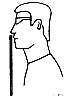
Figure 4
First measure the middle position. The installation position of the manikin is shown in Figure 4, so that the manikin is facing the release, and the nose tip of the manikin is 25 mm away from the plane outside the cabinet door.
Fix the measuring needle position of the detector so that the needle tip is located in the area between the nose and mouth on the face of the manikin, the long axis of the measuring needle is parallel to the cabinet door, and the height of the measuring needle tip from the ground is 1500 mm, as shown in Figure 5. The measuring needle shall be fixed with metal wire or ring frame clamp specially used in the laboratory. When the measuring needle is close to the breathing belt of the manikin, it shall ensure that the air flow pattern around the manikin is not disturbed and damaged.
The measuring needle is located in the breathing belt of the human body and parallel to the plane of the cabinet door
Figure 5
Open the tracer gas control valve.
Observe and consider the detector reading for 10 min, either manually or automatically. When manual recording is adopted, the reading shall be recorded every 2 minutes.
7.4.4. Rearrange the releaser and manikin positions on the left and right respectively. Repeat the test steps of 7.4.3 for each test location.
7.4.5. Calculation method
Calculate the average value of the readings at the three test positions, and take the maximum value as the control concentration of the exhaust cabinet.
The performance rating of the exhaust cabinet is expressed in the form of XX am YYY. XX refers to the release of trace gas, in L / min; YYY refers to the control concentration of exhaust cabinet, in ml / m3, and am refers to the working condition measured under laboratory conditions.
7.5 resistance test
7.5.1. Test conditions
The same as 7.4.1.1 and 7.4.1.2.
7.5.2. Test instrument
Pitot tube and inclined micro manometer within the calibration validity period.
7.5.3. Test method
A circular pipe with a diameter of 200 ~ 300 mm is connected at the top of the exhaust cabinet with a square round joint. The length of the pipe is 1400 ~ 2500 mm. A measuring hole is reserved on the circular pipe 800 ~ 1500 mm away from the joint. The layout of measuring points on the inner section of the pipe is shown in Figure 2.
Keep the wind speed on the exhaust cabinet at 0.4 ~ 0.5 m / s, measure the total pressure value and dynamic pressure value of each measuring point with pitot tube, and take the average value as the total pressure value p and dynamic pressure value PD in the pipeline respectively.
7.5.4. Calculation method
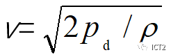
The velocity of the section of the measuring point is obtained from Formula 1, where R is the air density.
From the section velocity V, the local resistance of the square joint and the resistance of the round pipe in front of the measuring point are obtained.
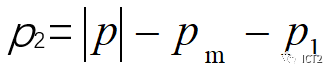
The resistance of exhaust cabinet is calculated by the following formula:

Where: P2 - resistance of exhaust cabinet, PA;
P -- total pressure value of measuring point, PA;
PM -- local resistance of square round joint, PA;
P1 -- resistance along the way of the circular tube in front of the measuring point, PA.
7.6 flow display test, surface wind speed measurement test, control concentration test, resistance measurement test and make-up air volume test shall be in accordance with the relevant provisions of Chapter 7.
7.7 insulation resistance test: under normal temperature and humidity conditions, measure the insulation resistance between the live part and non live metal part of fan coil with 500 V insulation resistance meter.
7.8 Test of paint film adhesion: take any area of 10mm long and 10mm wide on the external surface of the box, draw 11 parallel cuts vertically and horizontally with a new shaving blade, with an interval of 1mm and a depth up to the substrate, and evaluate with the ratio of the number of cells of paint film falling off within the scratch range to 100. If the paint film of each cell is retained less than 70%, it shall be regarded as falling off.
8 Inspection rules
8.1 the inspection of exhaust cabinet is divided into delivery inspection, type inspection and sampling inspection.
8.1.1. Type inspection shall be carried out under one of the following conditions:
A) new products manufactured or old products produced by transfer;
B) after formal production, when there are major changes in structure, process and materials that may affect product performance;
C) when the product is produced again after three years of shutdown.
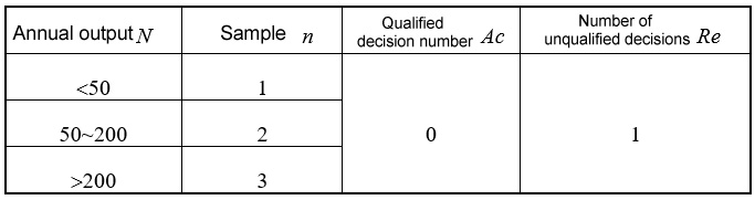
8.1.2. Various inspections of exhaust cabinet shall be in accordance with table 5.
8.2. The sampling inspection of exhaust cabinet shall be in accordance with table 6.
Table 5

Table6
9 Marking, packaging and storage
9.1. The label of each exhaust cabinet shall comply with the relevant provisions of GB / T 13306, and shall be marked with the following contents:
A) name of manufacturer;
B) product model and name;
C) main technical parameters: surface wind speed, resistance and overall dimension;
D) date of manufacture;
E) product number.
9.2. Each exhaust cabinet shall be pasted with a trademark on the obvious part.
9.3. The exhaust cabinet shall be packaged according to the relevant provisions of JB / T 9065.
9.4. The exhaust cabinet shall be stored in a dry and ventilated warehouse to prevent the products from being bumped.