


Hotline
400 666 9939
How to Design A Safe and Energy-saving Laboratory Exhaust System?
Date: 2022-01-19 Source: RUANQI Classification: Resources
Brief Introduction
The laboratory exhaust system can not only clean the polluted air in the laboratory and fume hood, but also safely discharge the exhaust gas out of the building, so that harmful and odorous smoke will not re-enter or affect the surrounding sensitive locations (receivers) through the air inlet. This is achieved by increasing the appropriate combination of chimney height and exhaust momentum, that is, plume lifting. The lower the chimney height, the greater the plume rise, so more air volume is needed to safely transport the exhaust gas away from the building. Or, if the exhaust chimney is higher, the plume will rise less and the required air volume will be less.
The design of laboratory exhaust pipe is usually based on the empirical rules 1,2,3,4 described in various standards and best practice guides; Generally, the minimum chimney height (3 m to 1.25 times the height of the building) and the outlet speed (10 m/s to 15 m/s) are defined. Unfortunately, the chimney height and outlet speed alone are not enough to define whether the air quality is within the acceptable range at all nearby receiver locations.
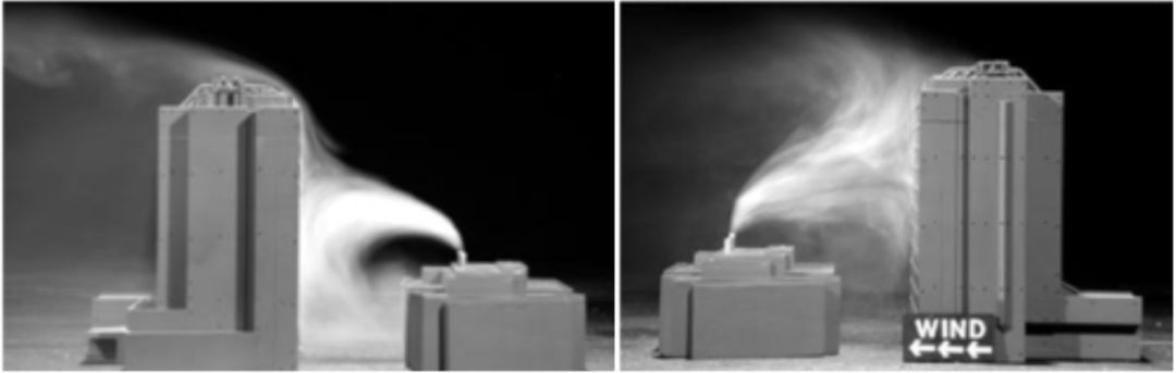
Figure 1: The flow field of the laboratory exhaust pipe is located in the upwind and downwind of the building. It can be clearly seen from the figure that determining the chimney design according to the rules will adversely affect the air quality of nearby air inlets.
The empirical rule should not be used, but the engineering analysis technology called exhaust diffusion model should be used to determine the correct combination of chimney height and exhaust volume. Decentralized modeling is used to predict the concentration distribution at sensitive locations in surrounding areas as a function of wind speed and direction. When the maximum predicted concentration is less than or equal to the design target, the exhaust system is considered acceptable, which is to ensure that the exhaust concentration remains below the published health limit and odor threshold 6,7,8.
In the wind direction and wind speed where the predicted concentration is lower than the design target, it is usually possible to reduce emissions and still achieve the design target, while saving a lot of energy. In order to define the most energy-saving exhaust system, physical diffusion modeling (i.e. wind tunnel modeling) should be used.
Determine the acceptable design goal of secondary entrainment of laboratory waste gas
In order to evaluate the acceptability of air quality, the dispersion modeling technique is used to predict the maximum concentration of exhaust plume existing in the nearby receiver position. However, this information is useless unless some maximum acceptable concentrations or design targets are specified. The air quality acceptability problem can be expressed as:
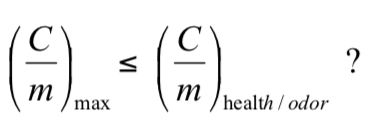
Where (C/m)max is the maximum predicted standardized concentration of the receiver's location (air inlet, operable window, pedestrian area, etc.), and (C/m)health/odor is any standardized health limit or odor threshold concentration. The left side (C/m)max of the chemical emission equation only depends on external factors, such as exhaust chimney parameters, receiver location and atmospheric conditions. The right side of each equation relates to emissions and is defined as the ratio of health limit or odor threshold (μg/ m3) to emission rate (g/s). Therefore, highly toxic chemicals with low emission rate may attract more attention than less toxic chemicals discharged at very high rate.
In practice, the list of chemicals of each exhaust type is checked to determine the appropriate values of (C/m) health and (C/m) odor of any released chemicals. Dispersion modeling is performed to determine the (C/m)max of various chimney height designs evaluated. Those designs that produce concentrations equal to or lower than the design target, that is, (C/m)max≤(C/m) target, are considered acceptable.
Dispersion modeling method
Using three different types of research, the concentration prediction (C/M) of sensitive locations can be completed with different degrees of accuracy:
1. Comprehensive field monitoring
2. Numerical simulation
3. Wind tunnel research with reduced scale.
1. Comprehensive on-site monitoring
The comprehensive field monitoring plan includes releasing tracer gas from exhaust system and measuring the concentration of downwind receiver. Although it can produce the most accurate exhaust behavior prediction, it is usually expensive and time-consuming. In addition, it can only be used in existing laboratory facilities. If the nature of the study is to estimate the maximum concentration of several chimneys in several locations, it may take years of data collection before measuring the maximum concentration related to the worst-case meteorological conditions.
2. Numerical dispersion modeling
Gaussian-based analytical model
The downwind concentration of exhaust plume can be calculated by using the Gaussian-based analytical diffusion model provided in ASHRAE Manual-HVAC Applications 4 and ASHRAE Laboratory Design Guide5. The model is designed for isolated rectangular buildings with roof chimneys, without considering the influence of adjacent buildings, elevated terrain or vegetation, which is enough to affect the airflow along the roof top. The model assumes that the emissions are not captured in the weak backflow area downwind of the building, so it should not be used for ground emissions with chimney height lower than the top of adjacent roof.
If used properly, ASHRAE dispersion model is designed to be conservative (i.e. low dilution/high concentration). However, it has been found that it is not conservative when the corner of the building is located directly in the straight windward direction between the chimney and the downwind air inlet 9, or when the chimney is located in the curtain wall 10. In addition, the dispersion model does not take advantage of the concentration reduction at the air inlet "hidden" from the exhaust chimney 11. Therefore, when using ASHRAE dispersion model, attention should be paid to ensure that the model is properly applied.
Computational fluid dynamics
Computational fluid dynamics (CFD) has been used for a long time to successfully simulate the internal flow fields in laboratories and zoos. Therefore, there is a natural tendency to try to use the same model for external airflow to simulate the performance of laboratory exhaust chimney. However, the simulation technology for indoor simulation is not suitable for simulating atmospheric turbulence. Because the dispersion of exhaust plume is directly related to atmospheric turbulence, even small errors in turbulence simulation can lead to large errors in predicted downwind concentration.
At present, the research on dispersion modeling using CFD model shows that unsteady simulation, such as large eddy simulation (LES), shows the greatest possibility. However, the LES model is more difficult and time-consuming to run, and even the results of LES simulation should be verified to verify its accuracy.
At this time, due to the above restrictions on the use of CFD for laboratory exhaust dispersion, it should be regarded as a research tool, rather than a design tool that can be used to correctly select the laboratory exhaust system.
3. Wind tunnel dispersion model
Wind tunnel modeling is usually the preferred method to predict the maximum concentration of chimney design and specific location, because it can provide the most accurate concentration level estimation in complex building environment. Wind tunnel model study is like a comprehensive field study, except that it is conducted in a controlled environment before or after the project construction. Usually, the scale model of the building under evaluation and the surrounding buildings and terrain within a radius of 300 meters are placed in the atmospheric boundary layer wind tunnel. Trace gas is released from a specific exhaust source, and then the concentration level of the gas is measured at a specific receiver position and converted into a full-scale concentration value. Next, these values are compared with appropriate design standards to evaluate the acceptability of exhaust design. ASHRAE 4 and EPA 13 provide more information about scale model simulation and test methods.
Wind tunnel research is very technical, so we should be careful when choosing a decentralized model consultant. Past experience, correct calibration of wind tunnel and technical qualification of employees are all very important.
Energy-saving laboratory exhaust system strategy
Compound laboratory exhaust system
Combines exhaust gases into a common exhaust system. Whether through exhaust manifold or very close chimney combination (the chimney must meet the requirements of exhaust plume in almost all wind directions), it will enhance the lifting of exhaust plume, thus reducing the downwind concentration of the receiver at a height lower than the chimney. Closely grouped chimneys can be used for special exhaust gases, such as perchloric acid and radioisotopes, which cannot be combined because of their chemical properties. Compared with installing exhaust nozzles on the chimneys of a single laboratory chemical fume hood, combined exhaust usually produces larger smoke plumes.
When most chemical emissions come from abnormal conditions or a large amount of emissions from a single laboratory chemical fume hood, the combined pipe of exhaust pipes can also provide some internal dilution of fume hood exhaust. This unsafe or large release condition is the main cause of odor and potential health effects.
Generally, the laboratory exhaust manifold is usually provided by multiple exhaust fans. The size of the fan is usually such that the building exhaust requirements can be met when one or more exhaust fans are turned off. In this case, the composite system provides redundancy in case of fan failure. This makes the integrated system of laboratory occupants safer than the single fume hood exhaust system. Overall, an integrated system has the following advantages:
Reduce capital and operating costs; Fewer exhaust chimneys; Greater design flexibility; Simpler wastewater treatment; Increase dilution and momentum; Reduce maintenance cost; Fan redundancy The potential of energy recovery; Less roof leakage; Reduce the total volume flow demand.
Exhaust control strategy of VAV laboratory
The laboratory is designed to use variable air volume (VAV) exhaust system to allow the exhaust ventilation system to match or almost match the supply ventilation airflow requirements of buildings. This enables designers to make full use of energy-saving opportunities related to adopting various strategies to minimize the airflow requirements of the laboratory. However, just as arbitrarily reducing the air supply flow may adversely affect the air quality in the laboratory environment, blindly converting the exhaust system into VAV may damage the air quality of nearby sensitive receivers (for example, air inlet, openable windows, laboratory space, etc.) without a clear understanding of the system performance. Therefore, before adopting VAV system, the potential operating condition range should be carefully evaluated through detailed decentralized modeling research, as mentioned above. Because the nature of these evaluations is to accurately determine the minimum volume flow requirements of the exhaust system, the preferred method is to use physical models in the boundary layer wind tunnel. Numerical methods can be used, but these methods usually produce the minimum volume flow when they are carried out correctly, thus reducing the energy-saving potential. The following describes two different strategies that can be used to operate the exhaust system of VAV laboratory.
Strategy 1: Simply turn down the VAV laboratory exhaust system
In the simple turn down VAV system, the exhaust flow is based on the larger of two values: the minimum air quality setpoint and the ventilation demand of the building. The minimum air quality setpoint is defined as the minimum volume flow rate/outlet speed/chimney height required to provide acceptable air quality at all sensitive receiver locations under the worst-case wind conditions, as defined in dispersion modeling assessment. During the evaluation period, when a simple downward adjustment VAV system is adopted, the chimney design usually pays attention to the minimum potential volume flow of the laboratory building rather than the maximum value evaluated for the constant volume exhaust system. A simple regulating system is preferably designed, in which the exhaust fan can completely regulate the volume flow to meet the minimum and maximum laboratory exhaust requirements. This enables the system to respond quickly to pressure deviations and eliminates the need for bypass dampers. This can usually be achieved by evaluating the number of chimneys in each plenum and the subsequent height requirements needed to completely eliminate the need for bypass air through VAV control and fan classification.
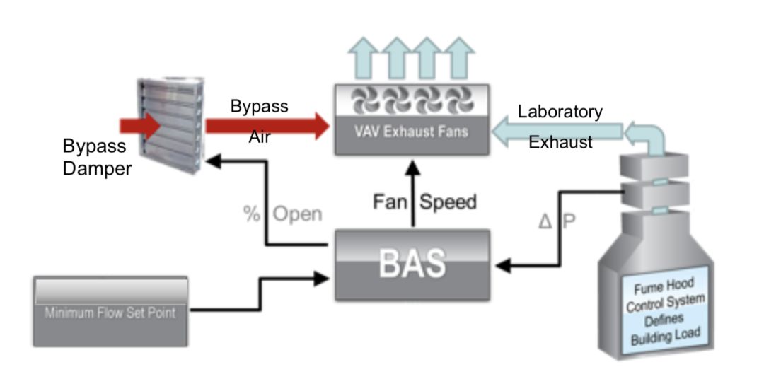
Fig. 2: Flow chart of simple downward adjustment of VAV laboratory exhaust system
Strategy 2: Wind response VAV laboratory exhaust system
If simply lowering the VAV system will not result in the minimum volume flow equal to or lower than the building ventilation demand, or if the chimney height required to reach these minimum volume flows is too high, it can be further optimized by applying the wind response VAV laboratory exhaust system.
In this strategy, the local anemometer is connected to the Building Automation System (BAS), and the required minimum exhaust flow is changed based on the current wind conditions (direction and speed). When the current wind speed and/or direction do not correspond to the worst-case conditions (as assumed in the simple regulation strategy), the exhaust system can be lowered to more closely match the building demand. Basically, specify the minimum set point for each wind direction/speed combination. This usually leads to the set point of the minimum volume flow of air being much lower than the building requirements of many wind conditions, allowing the whole ventilation system to operate at the best efficiency.
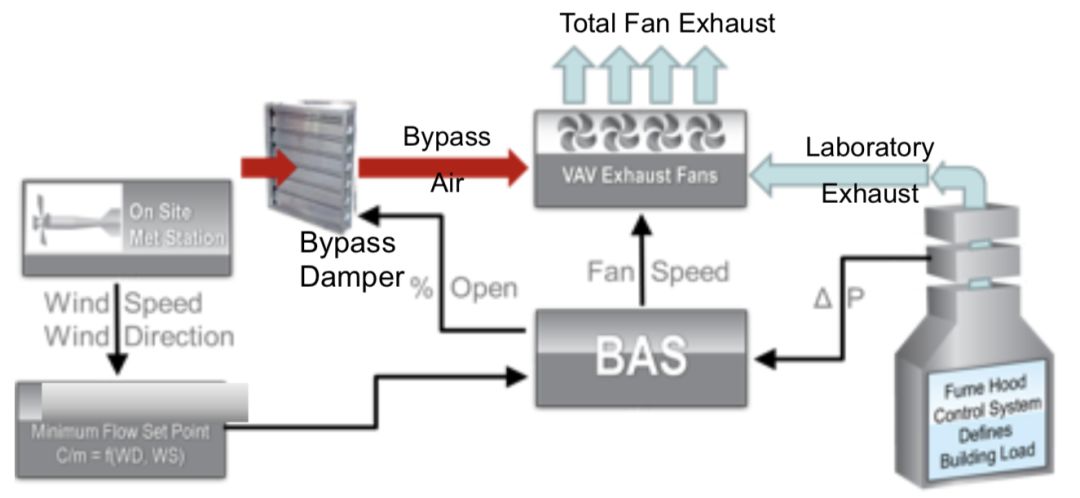
Figure 3: Flow chart of exhaust system of VAV laboratory for wind response
This strategy requires physical exhaust dispersion modeling in wind tunnel, because most numerical diffusion models do not provide off-axis concentration prediction. The minimum volume flow setpoint as a function of wind direction (WD) and wind speed (WS) requires concentration prediction at all sensitive positions (receivers) of all wind direction, wind speed, chimney height and exhaust flow parameters.
Summary and conclusion
Accurate evaluation of exhaust dispersion can be used to provide exhaust/intake design optimized for safety and energy consumption. No matter what type of exhaust system is used, the important design parameters are the height of physical chimney, volume flow rate, outlet speed, expected pollutant discharge rate and concentration level at sensitive positions. The overall performance should be evaluated with appropriate standards to ensure acceptable concentration in sensitive locations. When the VAV laboratory ventilation supply system is adopted in the laboratory, the design team should strongly consider the opportunity of including the exhaust system of VAV laboratory, so as to fully realize the energy saving potential of VAV control. However, blindly applying VAV to the laboratory exhaust system using the "rule of thumb" operating parameters may be harmful to the air quality of air inlets and other places of concern. Therefore, dispersion modeling evaluation should be carried out to determine the acceptable minimum volume flow. Any implementation of VAV exhaust system should include building automation system designed to handle appropriate control logic. In addition, the debugging of the system should include various operating conditions.
Reference
1. ANSI/AIHA, American National Standard for Laboratory Ventilation, Standard Z9.5-2011.
2. British Standards, BSI, Fume Cupboards. Safety and Performance Requirements, British Standard
BS EN 14175-2:2003, November 2003.
3. Australian/New Zealand Standard, Safety in laboratories, Part 8: Fume Cupboards, AS/NZS 2243.8:2014, January, 2014.
4. ASHRAE, ASHRAE Handbook-HVAC Applications, Chapter 45, Building Intake and Exhaust Design, American Society of Heating Refrigeration and Air Conditioning Engineers, Atlanta, GA 2015.
5. ASHRAE, ASHRAE Laboratory Design Guide, Planning and Operation of Laboratory Systems, Second Edition, American Society of Heating Refrigeration and Air Conditioning Engineers, Atlanta, GA, 2015.
6. ACGIH, Guide to Occupational Exposure Values, 2017.
7. ACGIH, Threshold Limit Values for Chemical Substances and Physical Agents, 2017.
8. ACGIH, Odor Thresholds for Chemicals with Established Occupational Health Standards, 1989.
9. Petersen, R.L., B.C. Cochran, and J.J. Carter, “Specifying Exhaust and Intake Systems,” ASHRAE Journal, August 2002.
10. Petersen, R.L., J.J. Carter, and M.A. Ratcliff, “Influence of Architectural Screens on Roof-top Concentrations Due to Effluent from the Short Stacks,” ASHRAE Transactions, Vol. 105, Part 1, 1999.
11. Petersen, R.L., J.J. Carter, and J.W. LeCompte, “Exhaust Contamination of Hidden vs. Visible Air Intakes,” ASHRAE Transactions, Vol. 110, Part 1, 2004.
12. Meroney, Robert, et.al., “Review of CFD Guidelines for Dispersion Modeling,” Fluids, Volume 14, 2016.
13. EPA, Guideline for Use of Fluid Modeling of Atmospheric Dispersion, April 1981.